 |
 |
| vacuum tube 6P45S | feedback coil, 15 turns |
 |
| WARNING! This circuit was blindly copied without my appreciation in a book V. Lysenko - HV supplies, pg. 137 - the bottom of TC secondary is connected to dangerous plate voltage source. I had connected primary and secondary together during my early experiments when I used the same TC with different drivers and some of them worked with grounded primary. |
This circuit works in pulse mode (only at + halfwave). It reduces the plate losses to less than 50%. As anode power supply I used transformer 2 x 300 V / 200 W, later I add other 300 V / 400 W transformer and then mains - all in serial connection. Resultant AC voltage was about 1100 V. I know that this isn't good idea but I cannot buy any suitable transformer in one. (1500 VAC / 500 VA will be great). You may short g2 resistor 18 kohm (but watch ig2 value) to get longer sparks. With this circuit (with PL504) I reached about 6 cm sparks. But plate of my small tube is going red hot in 30 seconds. My friend have a MOT but it will be killer for this tube. This is my last experiment. Now I'm trying to get more powerful parts.
8.6.2002 I bought the MOT from my fried. It is used as my new plate power supply. Output voltage is 2000 V / 800 VA but it's underdimensed and heats too much (with no load too). I'm using variac Křižík 500 VA in primary circuit to regulate output voltage. As a rectifier a use serial combination of 7 common 1N5407 diodes + MP capacitor 0,25 µF / 16 kV as filter (I don't have greater capacity yet). So I connected my old PL504 driver to the new power supply. I was turning variac and watching how the stream of sparks growing up from spike. Betweentimes the PL504 plate turned yellow and bulb melted through. Bulb was filled with air and game over. Then I heard only a crunching glass of cooling off tube. Sparks reach about 6 cm long.
 |
 |
 |
 |
 |
After PL504 death I tried another tubes: transmitting tetrode Telefunken RS685 and pentode RCA 813. But this tubes disappoint my expectation. The RS685 driver gives sparks same as SU169 transistor driver. The 813 driver was little bit better but didn't reach length of PL504 driver. But they survive this experiment (plates was little bit red too). The Problem is that this tubes have lower plate current (but have higher plate voltage). Last I tried the most powerful tube which I get - Russian 1kW transmitting tetrode GU-43B with 1 A plate current. I reached about 7 - 8 cm sparks with it. But my rectifier broke down - the end. I expected longer sparks with this driver so I hope that I will tune up it. I ordered good ceramic capacitors 1n8 / 3,8 kV for TC's primary circuit and 4 µF / 2,5 kV for power supply filter. Remains to get some high voltage diode. Also I will make some case for MOT and variac.
 |
 |
 |
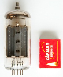
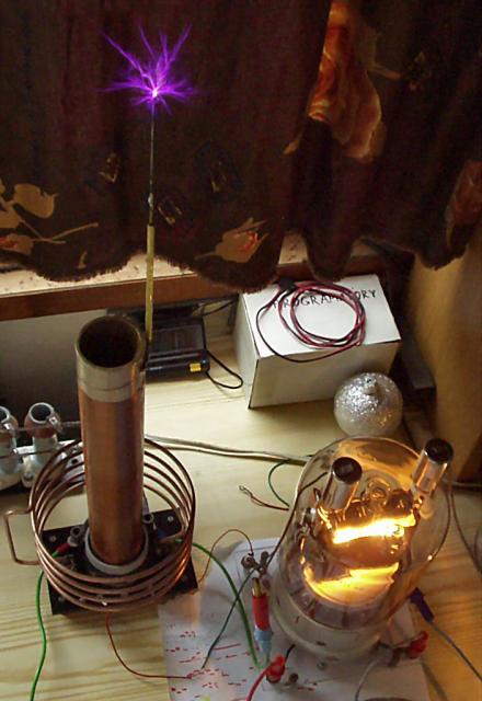
20.1.2003 I have a good luck today. I found an old Russian color TV using tubes. It was heavy-shredded wreck but 6P45S tube survived. So I took it out with nice ceramic socket. BTW the Russian firm Svetlana is still producing it as EL509/6KG6 for Hi-Fi and RF amplifiers. There's no major circuit modification needed-compared with one above. I only eliminated big filter cap (it run better without it) and replaced small tank capacitor by another better ceramic one (4 * 1,8 nF / 3,8 kV). As a HV rectifier I bought HV05-12 diode for microwave owens in GES-Electronic (~60 Kč). I used my favorite power supply circuit with variac and MOT. I could turn the variac to one half in safe mode while TC making about 4 - 5 cm sparks. Then I might turn the variac more only for a few seconds (to be able to take a photo) because plate turns red-hot. I measured that RMS power input was about 500 W (6P45S has plate power dissipation about 35 W). For this moment I reached about 7 - 8 cm sparks which was very hot and melted the spike of needle which I use as a discharge electrode. It made a hot blob of melted iron which sputter as a fire-cracker :-). So then I was trying to adjust g1 and g2 bias and tuning the tank circuit and grid circuit but with no better results. The tube is operating with maximum power and there's only one way to improve operation-shorten the active time in pulse mode to lower power dissipation. This mean make some SMPS for supplying MOT. I could take the photos with shorter exposition time because the sparks was quite bright. This enhanced details of stremers.
 |
 |
 |
 |
 |
11.2.2003 Here is a power supply modification for pulse mode which I mentioned above. I made a square wave from support supply using simple clamper circuit for TTL ICs. This signal is applied to 7493 counter (configured as binary divider) input. On its outputs is divided lower frequency but still with 1:1 duty cycle. So I use monostable flip-flop 74123 which shorten the pulses to about 10 ms. I use inverted output because current-boost transistor is inverting too. This signal drives power triac which release every 2nd, 4th, 8th or 16th period to the MOT XFMR. There is a single-wave rectifier on secondary side which pass through only positive halfwaves. This cause a 1:4 to 1:32 duty cycle. It lowers the plate power dissipation a lot. But too low frequencies causes the low spark "framerate" which doesn't look good. And the XFMR is not happy too. It is going hot in few minutes. Now I'm thinking about some grid1 modulation (connecting g1 to negative voltage).
 |
 |
 |
 |
After triac modulation experiments I tried a grid1 modulation by transistor. It worked quite well. MOT didn't heat like before. But there's one problem - it's not easy to buy PNP transistor with greater Vce than 300 V. For full grid blocking the higher voltage is needed. And there's need to use some extra power supply for negative base bias. Theoretically NPN transistor would be used but it requires floating source of driving impulses. This circuit works this way: If there's no voltage on trigger input the PNP transistor is opened (by negative bias supply) and shorts the grid1 bias supply about -310 VDC (via resistor). This mean that grid1 is grounded and tube is in active mode. When trigger input gets the positive TTL pulse it close the PNP transistor and it cause connecting grid1 to negative bias -310 VDC supply and tube is blocked. But with more plate power applied the transistor sometimes stays turned on independently on presence of driving pulse. It may be due to RFI or operating transistor's Vce little bit over limit (transistor didn't break).
22.6.2003 I finally bought a good tube - Russian direct-heated transmission pentode GU-81M. It hasn't such a big plate current as 6P45S but have more and more greater plate power dissipation. Unfortunately I didn't have a socket for it. So I made an improvisation from plexiglass and contacts of power rotary alteration switch. To get maximum power I need to remove g1 resistor. Plate circuit is powered through HV diode directly from MOT and g2 through variac and 220 > 600 V transformer (g2 has allowed 140 W power dissipation, plate 600 W).
Sparks run to 8 cm length. It's less than with 6P45S tube but GU-81M is not overheating and is capable to run long times (rather the socket would melted than electrodes). So it needs more powerful plate supply but what can I get better than a MOT? Some coiler from Romania reached 30 cm sparks with this tube (and larger TC). It can be seen that this tube has a great potential.
 |
 |
 |
18.8.2003 After I wounded BigTC I proved it immediately with GU-81M VTTC circuit. The circuit lays on the table so I only replace the TC. I was full of expectations. I started to turning up my variac and spark stream rise quickly. When I turned variac to 1/3 the sparks had about 7 cm length so it was looking good. But with next voltage rising at g2 the growth speed was fading. When I turned variac to maximum the sparks was only 12 cm long. I expected little bit more. It would require more powerful supply. Maybe two MOTs in series but there's a problem because one MOT's secondary terminal is internally connected to MOT's core. Or maybe a voltage doubler. But now I have a lot of troubles with my MOSFET SSTC half-bridge.
 |
 |
 |
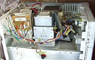
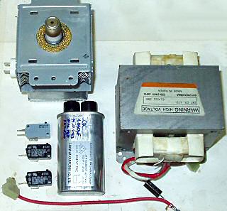
19.9.2003 This day I had a good luck. I found a trashed microwave oven which I disassembled immediately. May be it worked. I tried everything except the magnetron :). But I didn't enjoy my el. parts for a long time (see below). I got a MOT 220V > 2200 V, capacitor 1,05 µF / 2100 VAC, HV rectifier HVR-1X and magnetron GoldStar 2M214:
 |
 |
 First I wanted to connect both my MOTs in series but when I saw poor paper insulation between
primary and core I rather tried to make a voltage doubler. I used big MP 2 µF / 6k VAC capacitor
and HV05-12 diode. So I connected my GU-81M VTTC and turn variac to the max. But any spark length doubling was not happened.
I reached about 15 cm. The sparks was thicker and hotter. And GU-81M's plate was getting pretty hot. When I was trying
to draw arc with a screwdriver the HV diode suddenly exploded and one fragment hit my finger (luckily not eyes).
Damned... I probably make a mistake that I din't blocked the diode with any capacitor (when I used RF blocking cap.
before it negatively affected spark length). It got some kickback from TC primary which rised when I stared to draw arc.
But I have one more from microwave owen...
First I wanted to connect both my MOTs in series but when I saw poor paper insulation between
primary and core I rather tried to make a voltage doubler. I used big MP 2 µF / 6k VAC capacitor
and HV05-12 diode. So I connected my GU-81M VTTC and turn variac to the max. But any spark length doubling was not happened.
I reached about 15 cm. The sparks was thicker and hotter. And GU-81M's plate was getting pretty hot. When I was trying
to draw arc with a screwdriver the HV diode suddenly exploded and one fragment hit my finger (luckily not eyes).
Damned... I probably make a mistake that I din't blocked the diode with any capacitor (when I used RF blocking cap.
before it negatively affected spark length). It got some kickback from TC primary which rised when I stared to draw arc.
But I have one more from microwave owen... |
 |
 |
 |
 |
7.11.2003 My friend lent me for my experiments Russian pulse indirect-heated tetrode GMI-90 (I heard that it was used in radar systems). At first look it take up with its unusual design. It contains two independent electrode systems in one envelope. Filament and cathodes have separate leads (there's a bug in datasheet - cathodes are NOT connected together). Grids are wired in parallel together and plate is common surrounding both systems from outside and inside. It may be heated either in serial (50 V / 3,5 A) or parallel (25 V / 7 A). There's only given peak plate current 36 A @33 kV peak plate voltage with 3 µs pulse duration. But plate power dissipation is only 140 W. I measured about 1,5 A average current with 2,2 kVAC halfwave rectified voltage applied to plate and 300 VDC at G2 and 0 V at G1. It sounds very good nearly impossible. As well MOT was heating and plate glow it might be real. So I connected tube in the same circuit as GU-81M and applied power.
Sparks was shorter than with GU-81M. But MOT was heating too much. When I wanted to pull up the power cord from the wallplug I felt insulation flowing between my fingers. One wire of powercord was melted. Hmm, something goes wrong... Otherwise I used undersized powercord rated for 2,5A only but this have never happened to me. So I took off the MOT on balcony to let it cooling. BTW even at around zero outer temperature it was cooling longer than an hour. I took my older MOT and tried to increase grid 1 resistor. I chose few resistors and tried to connect them while TC was running. I heard strange pops from MOT while I was attaching and detaching Rg1. And at once I looked on MOT which was in smoke. That pops was a flashovers in MOT secondary winding which burned insulation through. It cannot be repaired. Once the insulation is carbonized it's all useless and there's no point in rewounding :-(.
Next day I started to experiment again (by watchword "never mind, we have another one" :) with newer cooled MOT. I told myself that I will be more careful now. I inserted sense resistor 2R7 in cathode circuit to be able to watch the cathode current on oscilloscope. I begun with high Rg1 and Cg1 value. It was not oscillate by classical way but near every 2 second it sputtered shortly. And I seemed to hear that pop sound again. So I turn it off immediately and decreased Rg1. During the next run it was sparking near the normal way but MOT started to heating nevertheless I didn't see any DC component of plate current. this is really strange. After further lowering Rg1 when I increase Ug2 suddenly I saw the flashover on the MOT. And It started to smoke. In this case it can be clearly seen the hole in secondary insulation which was melted through by spark jumping to core. I cannot estimate the secondary voltage peak but it might be over 10 kV. But HV diode survived. In some future experiment (if I get another MOT) I'll try to make safety sparkgap on secondary side. I hope it will protect MOT against overvoltage. So now I cannot continue (probably for longer time :-(.
 |
 |
 |
 |
 |
VTTC lives again (VTTC II)
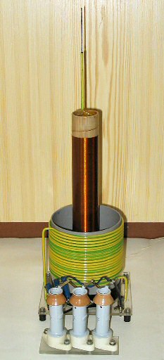 |
24.2.2004 After blowing my MOTs one colleague from school contacted me that he have some MOT. I got it for free so I thank him here again. But I had time for further VTTC experiments about 2 months ago. I decided to drive my BigTC by semiconductors only so I have aimed to my first smaller TC. I also got some valuable suggestions for better VTTC construction from Italian coiler Fabio Mc Gyver. And this couldn't be done without primary coil redesign...
When I was winding my first TC I didn't know about VTTC yet. I had wound primary coil by few turns of thick solid wire. It would be good for classic spark-gap TC if any flashovers from top primary turn to secondary wouldn't occur. The main problem was small primary coil inductance which cause small load impedance. I found that turns ratio is not much important thing but impedance match is.
Impedance of parallel LC circuit tuned to resonance is theoretically infinity but in real world it is limited by losses (alternate parallel resistor Rp0). This resistor is not a real part in the circuit and cannot be measured easily. But it can be calculated from Q-factor of given parallel LC circuit: Rp = Q*Xl = Q*Xc, where Xl and Xc is inductive resp. capacitive reactance [Xl = 2*Pi*f*L, Xc = 1/(2*Pi*f*C)]. So we need to know the Q-factor. It is strongly dependent on operating conditions. Increasing the sparks cause decreasing the Q-factor. When I measured it from frequency response as Q = f0/B, where B is a bandwidth determined by -3dB impedance decay I got Q ~ 60. Then I measured Q-factor under operation as a circulating current to common current ratio and I got Q ~ 30 for 1cm sparks. Original primary circuit impedance was very low, only about 420 ohms. Because vacuum tubes have internal resistance from several kiloohms up to tens of kiloohms (relatively small plate current compared to plate voltage) the load was not matched to them. This caused that most of energy was lost (heated) in the tube instead to be transfered to the load.
So I unmounted (with tears in my eyes ;) original primary coil, which I was winding that time so hard on a glass, and took a cut-off of 11cm dia PVC pipe and began experimenting with number of new primary's turns. The best result I reached with around 18 turns when inductance was more than 10-times greater than with original primary coil. So I bought 7 meters of copper insulated wire with 4 mm 2 core cross section and wounded it on truncated PVC pipe - 18,3 turns. Here are details of windings. Now I got for Q = 30 that Rp0 is around 6000 ohms so this should make tube much more happy. I also recalculated and decreased tank capacitor from 10,7 nF to 0,76 nF. But I reached better results with around 0,9 nF. While TC is sparking then not only Q-factor goes down but secondary resonant frequency too (conductive plasma of the discharge behaves like a metal toroid and increase secondary capacitance). So it's a good idea to set primary resonant frequency little bit lower under secondary f0 to make it fully tuned when larger sparks come up. In my case the frequency has dropped from ~1,2 MHz to 0,95 MHz. Then I wounded a new 20 turns feedback coil with taps at 10th and 15th turn at the bottom of the pipe. I also revarnish secondary coil with one layer of acrylic spray. The base is made of acrylic glass again but now the secondary coil is only tight inserted to base hole instead to be glued. It allows me to easy remove secondary and use it with other primary.
I used my favorite tube GU-81M for driving new VTTC powered by MOT and g2 from variac:

After experimenting with grid circuit I found that I get maximum sparks with g1 directly connected to feedback coil at 10th turn. I'm wondered that with more feedback turns the sparks getting shorter (only 2/3 at 20th turn). When I connected g1 via parallel RC network the sparks was larger at 15th or 20th turn but still shorter and less flamy than with direct connection. G1 is not visually getting hot. Despite of previous operation it now works better with 1µF filter capacitor from microwave oven which together with 1nF RF blocking capacitor protects the MOT against HV spikes. So MOT seems not to be going to pop and blow now. Maximum reached spark length is 15 cm free to air and 17 cm to grounded object.
 |
 |
 |
14.9.2008 At this summerfall I went to visit radioamateur's meeting in Holice again. It is held annually. Weather was nice, I met some friends and also I bought russian transmitting triode GU-5B. It's quite heavy piece of tube with copper fan-tracery over the anode. It can dissipate 2,5 kW on anode but it demands min. 250 W for cathode heating. I looked forward to VTTC construction with this nice triode. At first I had to make a socket for it. It's very hard to find some for such tube and if it appears the price usually exceeds price of whole tube.
I have some free time this Sunday so I bring up the supported driller and other tools and started to working. Because of heavy filament current (up to 27 A) I decided to use a short 20 x 10 mm aluminum bars for holding tube pins to make it robust. Bars will hold the tube on place and also carry current from side plugs to pins. As usually I mounted it on 5mm acrylic glass base. This construction seemed to be very simple but it took me some hours. Especially when I broke a 2,5mm drill in one aluminum bar hole. Unfortunately in the hole for tighten screw making bar tight over a tube pin (there was no place for another hole beside). I was trying to get it out from the bar for an hour but without success so I rather made new bar. In the evening I cut out screw-threads in bar holes and mounted all together. The "final settling" of GU-5B has begun. When I had tightened screws for holding tube pins I heard a glass-crackling noise and I screamed "FUCK!". I removed the socket and see the fresh crack spreading from metal pin sealing to glass bottom of the tube. At the moment I tried to apply a glue to stop sucking air inside the tube but it was too late. When I applied 1200 V from voltage multiplier between anode and cathode a glow discharge appeared, R.I.P...
So I turned the triode into big crappy glowing tube :(. Now I begin to understand such high pricing of original sockets - a good socket will save money for new tube. So take this chapter as a warning and don't build a socket this way. I have to notice that when I looked attentively to tube pins it can be seen they are not exactly vertical from the base and parallel each other but I drilled precisely. So there were some side forces to pins. In case of e.g. GU-81M it wouldn't happen because it have a short litz wires between sealed terminals and connecting pins. When someone would have a spare GU-5B I will buy it and try again :)
 |
 |
 |
 |